Applications for Axial Movement
The figure below typifies good practice in the use of a single expansion joint to absorb axial pipeline expansion. Note the use of one expansion joint between two main anchors (MA),the nearness of the expansion joint to an anchor, the closeness of the first alignment guide (G1),the spacing between the first alignment guide and the second alignment guide (G2),and the spacing of the intermediate guides (G) along the balance of the line. Click here to see our guide spacing chart.
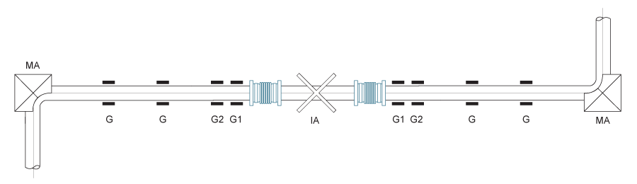
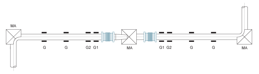
The figure below typifies good practice in the use of a double expansion joint to absorb axial pipeline expansion. Note the addition of the intermediate anchor (IA) which, in conjunction with the two main anchors, divides the pipeline into individual expanding sections, so that there is only one expansion joint between any two anchors. Note also the closeness of the first alignment guide (G1) to each expansion joint, the spacing between the first alignment guide and the second alignment guide (G2),and the spacing of the intermediate guides (G) along the balance of the each pipe section. For further information see our guide spacing chart.
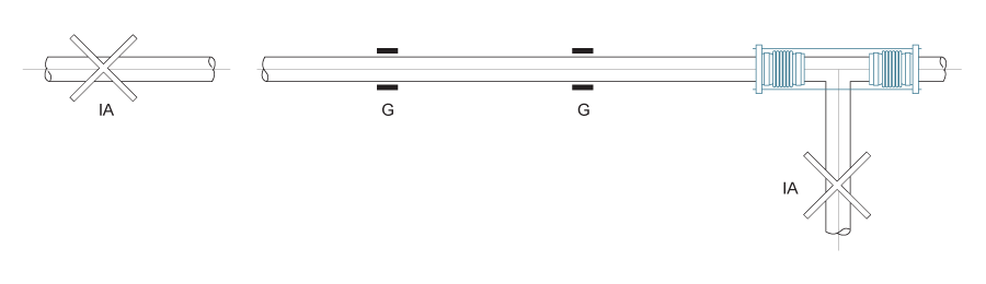
The figure below typifies good practice in the use of expansion joints to absorb axial pipeline expansion in a pipeline with a branch connection. The anchor at the junction, which in this case is a tee, is a main anchor (MA),designed to absorb the thrust from the expansion joint in the branch line. Note the nearness of each expansion joint to an anchor, the closeness of each first alignment guide (G1),the spacing between the first alignment guide and the second alignment guide (G2),and the spacing of the intermediate guides (G) along the balance of the each pipe section. Click here to see our guide spacing chart.
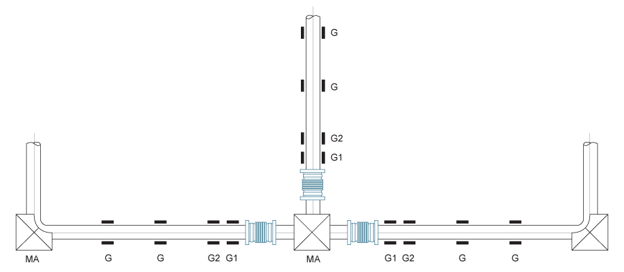
The figure below typifies good practice in the use of expansion joints to absorb axial pipeline expansion in a pipeline containing a reducer. The anchor at the reducer is the main anchor (MA),designed to absorb the difference in the thrusts of the expansion joints on each side of the reducer. Note the nearness of each expansion joint to an anchor, the closeness of each first alignment guide (G1),the spacing between the first alignment guide and the second alignment guide (G2),and the spacing of the intermediate guides (G) along the balance of the each pipe section. For further information see our guide spacing chart.
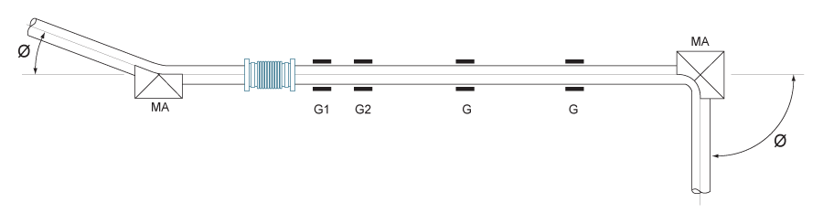
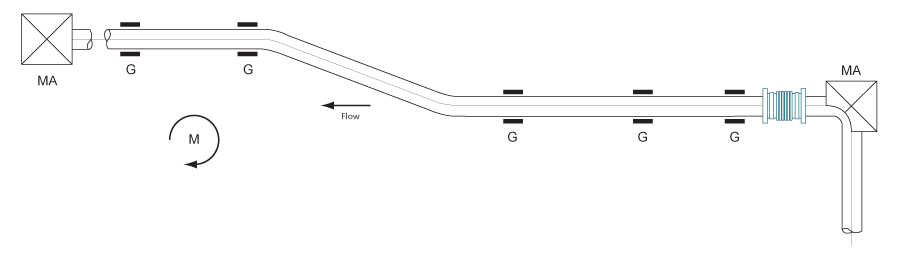
The figure below shows the application of a single expansion joint to a pipeline containing an offset. it should be noted that applications of this type are not usually recommended and will perform satisfactory only within certain limits. As in the first figure, the line is provided with main anchors at each end to absorb the pressure, movement loading, and guide friction. Where the line contains an offset, this load must first be transmitted through the offset leg, resulting in a moment on the piping. Where the line size is small, the offset appreciable, or where the pressure and movement forces are relatively high, this configuration may result in over stressing, or distortion of the piping and guides.
Note the nearness of each expansion joint to an anchor, the closeness of each first alignment guide (G1),the spacing between the first alignment guide and the second alignment guide (G2),and the spacing of the intermediate guides (G) along the balance of the line. Guides should be installed near both ends of the offset leg to minimise the effects of the bending moment on the system. For spacing of other guides see our guide spacing chart.
The figure below typifies good practice in the use of a pressure balanced expansion joint to absorb axial pipe line expansion. Note that the expansion joint is located at a change in direction of the piping and that the elbow and the end of the pipeline are secured by intermediate anchors. Since the pressure thrust is absorbed by the expansion joint itself, and only the forces required to deflect the directional guiding adjacent to the expansion joint, as shown, may suffice. In long, small diameter pipe lines, additional guiding may be necessary.